CIP Unit
What is a CIP Unit?
Working Principle of a CIP Unit
The CIP unit operates automatically throughout the entire CIP cleaning cycle. The CIP system efficiently controls tank filling, heating, and detergent dosing to achieve the required CIP cleaning conditions before the cycle even begins.
Depending on your specific process requirements, the CIP cleaning cycle may include a combination of the following CIP steps
First Pre-rinse
Hot alkali cleaning / Cold alkali cleaning
Intermediate rinse
Hot acid cleaning / Cold acid cleaning
Final rinse
Chemical cold disinfection
Hot water sterilization
Benefit o a CIP System
Integrating a CIP system into your facility offers numerous operational advantages
Efficient cleaning without equipment disassembly
Consistent and repeatable cleaning cycles
A CIP system actively helps reduce water and chemical consumption.
Suitable for hygienic liquid processing plants
Can be customized to your process requirements
Cleaning timers are only started when the desired cleaning temperature and detergent concentration are obtained into the return line. A conductivity sensor controls the concentration of detergent and detects the phase transition water/detergent. The flow detection indicates when an object is empty and offers a control on the return of cleaning liquid from the object in cleaning.
All relevant parameters are displayed and can be adjusted from the operator panel for example

Temperatures

Flow rate and volume

Cleaning timers

Detergent concentration

Ratio of recovered detergent

PID controller parameters

Cleaning mode
The INTE-FLUSH - Modular unit can operate independently. They depend on the detergent tanks only for solution supply, the circulation is established over the unit's circulation tank. They combine the benefits of centralized control with the advantages of decentralized operation.
System Information
Sizes and Capacity
Technical Data of Equipment in Circuit Unit (Basic type)
Optional Equipment
Control Module
Capacity range:
- up to 8 m3/h DN 40
- up to 16 m3/h DN 50
- up to 24 m3/h DN 65
- up to 50 m3/h DN 80
CIP pressure: max 4 bar
Temperature difference:
approx. 15-20 °C
Steam pressure: max 6 bar 300 kg up to 1500 kg/h
Compressed air: min 5 bar
Water: depending on capacity
- Circulation tank
- Supply pump with frequency inverter
- Tubular heat exchanger
- Instrument
- Set of actuated butterfly valves
- Set of service valves
- Complete internal piping ready fir connection
- Stainless steel frame
- Control module
- Materials in contact with liquids: 316L
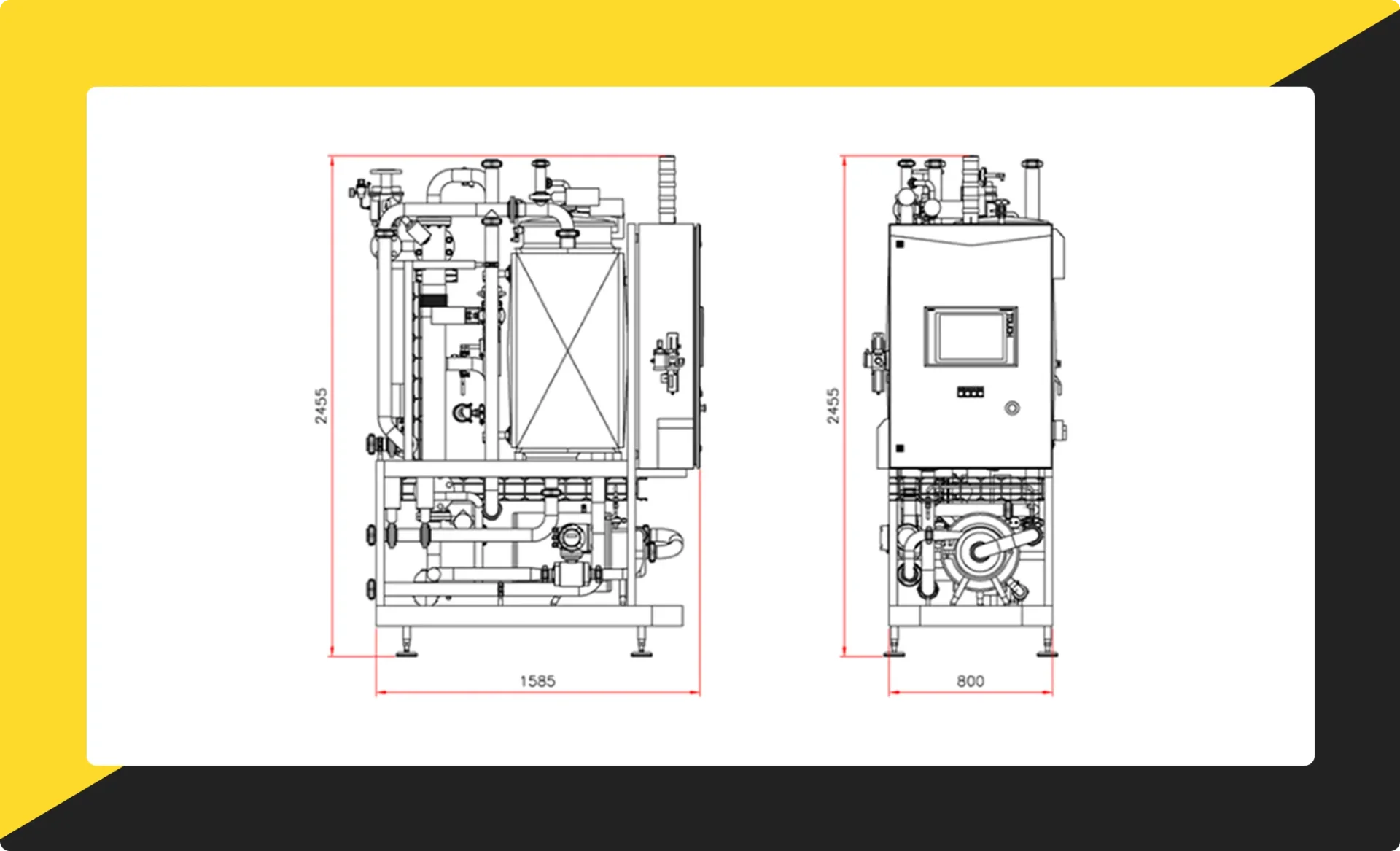
- Dimension: 800 x 1500 x 2400 mm (W x L x H)
- Level switches/transmitter for supply tanks
- Chart recorder for monitoring and recording temperature, conductivity, and flow rate.
- Feedback of remote valve
- Dosing pumps
- I/O communication to CIP objects
- Steam PRV station
- Air condition for control panel
- Air blow function
- Printer
- SCADA
- Remote control panel
- High supply tressure
- Stainless steel panel
- Protection class IP65
- Control voltage 24 VDC
- 12" TFT touch screen, 16K colors SIEMENS IPC with Windows OS
- CPU SIEMENS 1500
- Digital and analog inputs/outputs
- TIA programming software
- USB printer interface
- PROFINET bus
- Dimension: 800 x 1200 x 300 mm (W x H x D)

 MakeWebEasy
- Home Home
- Company Company
- Engineering Engineering
- Product Product
- Service & Support Service & Support
- References References
- Contact us Contact us